Connecting sensors
This section explains how to read sensors on JVRC-1 model.
Open a project file
Choose “Open...” in “File” menu and select a project file for JVRC-1. Its name is samples/tutorials/cnoid/sample3.cnoid.
Sensors defined in JVRC-1 model
You can find sensors defined in the JVRC-1 model by opening samples/tutorials/JVRC-1/main.wrl with a text editor. For example, you can find an accelerometer and a gyrometer as follows.
DEF JVRC Humanoid {
  humanoidBody [
    DEF PELVIS Joint {
      jointType "free"
      translation 0 0 0.854
      children [
        DEF PELVIS_S Segment {
       mass 10
       centerOfMass -0.01 0 0.034
       momentsOfInertia [0.08958333333333333 0 0 0 0.08958333333333333 0 0 0 0.11249999999999999]
       children [
            DEF gsensor AccelerationSensor {
              sensorId 0
            }
            DEF gyrometer Gyro {
              sensorId 0
            }
         Inline { url "pelvis.wrl" }
       ]
     }
We can find force sensors, named rfsensor, lfsensor and so on.
DEF rfsensor ForceSensor {
  sensorId 0
}

DEF lfsensor ForceSensor {
  sensorId 1
}
We can find cameras named rcamera and lcamera, and a range sensor named ranger.
DEF NECK_P Joint {
  jointType "rotate"
  jointAxis "Y"
  jointId 17
  ulimit [1.0471975511965976] #+60
  llimit [-0.8726646259971648] #-50
  uvlimit [ 5.75958]
  lvlimit [-5.75958]
  rotorInertia 0.0596
  children [
    DEF NECK_P_S Segment {
      mass 2
      centerOfMass 0.01 0 0.11
      momentsOfInertia [0.00968 0 0 0 0.00968 0 0 0 0.00968]
      children [
        Inline { url "head.wrl" }
      ]
    }
    DEF rcamera VisionSensor {
      translation 0.1 -0.03 0.09
      rotation      0.4472 -0.4472 -0.7746 1.8235
      frontClipDistance 0.05
      width 640
      height 480
      type "COLOR"
      sensorId 0
      fieldOfView 1.0
    }
    DEF lcamera VisionSensor {
      translation 0.1 0.03 0.09
      rotation      0.4472 -0.4472 -0.7746 1.8235
      frontClipDistance 0.05
      width 640
      height 480
      type "COLOR"
      sensorId 1
      fieldOfView 1.0
    }
    DEF ranger RangeSensor {
      translation 0.1 0.0 0.0
      rotation      0.4472 -0.4472 -0.7746 1.8235
      sensorId 0
      scanAngle 1.5707963267948966
      scanStep 0.011344640137963142
      scanRate 100
      minDistance 0.1
      maxDistance 30.0
    }
  ]
} # NECK_P
You can find data types for each sensor in the following page.
Data type for an accelerometer is TimedDoubleSeq and its length is 3. It contains accelerations in x,y and z directions.
Data type for a gyrometer is TimedDoubleSeq and its length is 3. It contains angular velocities in x,y and z directions.
Data type for a force/torque sensor is TimedDoubleSeq and its length is 6. 3 components out of 6 are for forces in x,y and z directions and the other 3 are for torques around x,y and z axes.
Data type of the camera image is Img::TimedCameraImage.
https://github.com/s-nakaoka/choreonoid/blob/master/src/OpenRTMPlugin/corba/CameraImage.idl
Img::TimedCameraImage is defined as follows.
enum ColorFormat
{
  CF_UNKNOWN, CF_GRAY, CF_RGB,
  CF_GRAY_JPEG, CF_RGB_JPEG // local extension
};

struct ImageData
{
  long width;
  long height;
  ColorFormat format;
  sequence<octet> raw_data;
};

struct CameraImage
{
  RTC::Time captured_time;
  ImageData image;
  CameraIntrinsicParameter intrinsic;
  Mat44 extrinsic;
};
struct TimedCameraImage
{
  RTC::Time tm;
  CameraImage data;
  long error_code;
};
data.image.raw_date contains width x height pixels. Definition of a pixel depends on the pixel format specified by format field. Cameras on JVRC-1 have 640 pixel width and 480 pixel height. Therefore raw_data contains data for 640x480 pixels.
Data type of a range sensor is RTC::RangeData.
typedef sequence<double> RangeList;
struct RangeData
{
    /// Time stamp.
    Time tm;
    /// Range values in metres.
    RangeList ranges;
    /// Geometry of the ranger at the time the scan data was measured.
    RangerGeometry geometry;
    /// Configuration of the ranger at the time the scan data was measured.
    RangerConfig config;
};
Measured distances from right to left are stored in ranges. If measurement of distance fails 0 is stored.
Enable cameras and range sensors
To enable cameras and range sensors in simulation, do the following settings.
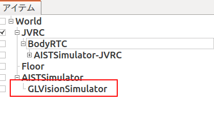
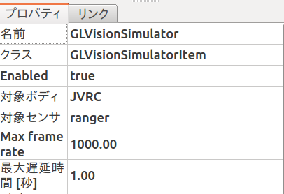
Select AISTSimulator in the item view and create a GLVisionSensorSimulator item and name it GLVisionSimulator.
Note
「対象ボディ」プロパティおよび「対象センサ」プロパティを空のままにしておくと、シミュレーション世界に存在するすべてのセンサがシミュレートされます。一方でこれらのプロパティを下図のように設定するとシミュレートするセンサを限定することができ、シミュレーション速度を向上させることができます。この例ではJVRCのrangerのみをシミュレーション対象としているため、頭部のカメラはシミュレートされないことになります。
A configuration file for BodyRTC
In the previous tutorials, data ports are connected automatically Choreonoid. But this function only works with simple port configurations.
Since the port configuration of RTC used in this tutorials is complex, we need to create a configuration file. Please create a file that contains the following lines and name it “RobotSensorsJVRC.conf”. And put it in /usr/lib/choreonoid-1.5/rtc.
out-port = q:JOINT_VALUE
out-port = gsensor:ACCELERATION_SENSOR
out-port = gyrometer:RATE_GYRO_SENSOR
out-port = lfsensor:FORCE_SENSOR
out-port = rfsensor:FORCE_SENSOR
out-port = rcamera:rcamera:CAMERA_IMAGE
out-port = lcamera:lcamera:CAMERA_IMAGE
out-port = ranger:RANGE_SENSOR
in-port = u:JOINT_TORQUE
connection = q:RobotControllerRTC0:q
connection = u:RobotControllerRTC0:u
out-port means defintion of a output data port. Its right hand value consists of two values separated by comma. The first value is name of port and the second value is data type.
in-port means definition of an input data port.
connection defines a connection between data ports. For instance, q:RobotControllerRTC0:q means to connect this RT component and RobotControllerRTC0.
You can find details of the configuration file format in the following page.
Setup the controller
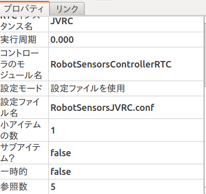
Select BodyRTC in the item view and set value of its property, “Configuration mode” and “Configuration file name” to “Use Configuration File” and “RobotSensorsJVRC.conf” respectively.
ビューアコンポーネントの起動・接続
ターミナルを2つ開き、それぞれ次のコマンドを実行します。CameraImageViewerCompはカメラ画像を受け取って表示するRTC、RangeDataViewerCompはレンジセンサの距離データを受け取って表示するRTCです。
$ CameraImageViewerComp
$ RangeDataViewerComp
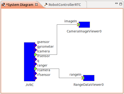
RTSystemEditorを起動してName Service Viewを確認すると、CameraImageViewer0、RangeDataViewer0というRTCが見つかるはずです。これらをSystem Diagramにドラッグアンドドロップし、次図のようにデータポートを接続します。
Run simulation
シミュレーションを開始すると、ウィンドウが2つ現れ、それぞれロボットに搭載されたカメラからの画像とレンジデータが計測した距離情報が表示されます。
A sample project used in this tutorial
You can find a sample project file created by this tutorial in samples/tutorials/cnoid/sample4.cnoid.